 Cross Section
Use the cross-section tool to inspect a vertical profile of the surface and vector elements along a defined line.
To create a cross-section line, select Cross Section from the Tools menu. Define the start point of the reference line by clicking on the canvas. A preview line is displayed as the cursor is moved, allowing accurate positioning of the reference line. Click the second time to define the reference line end point.
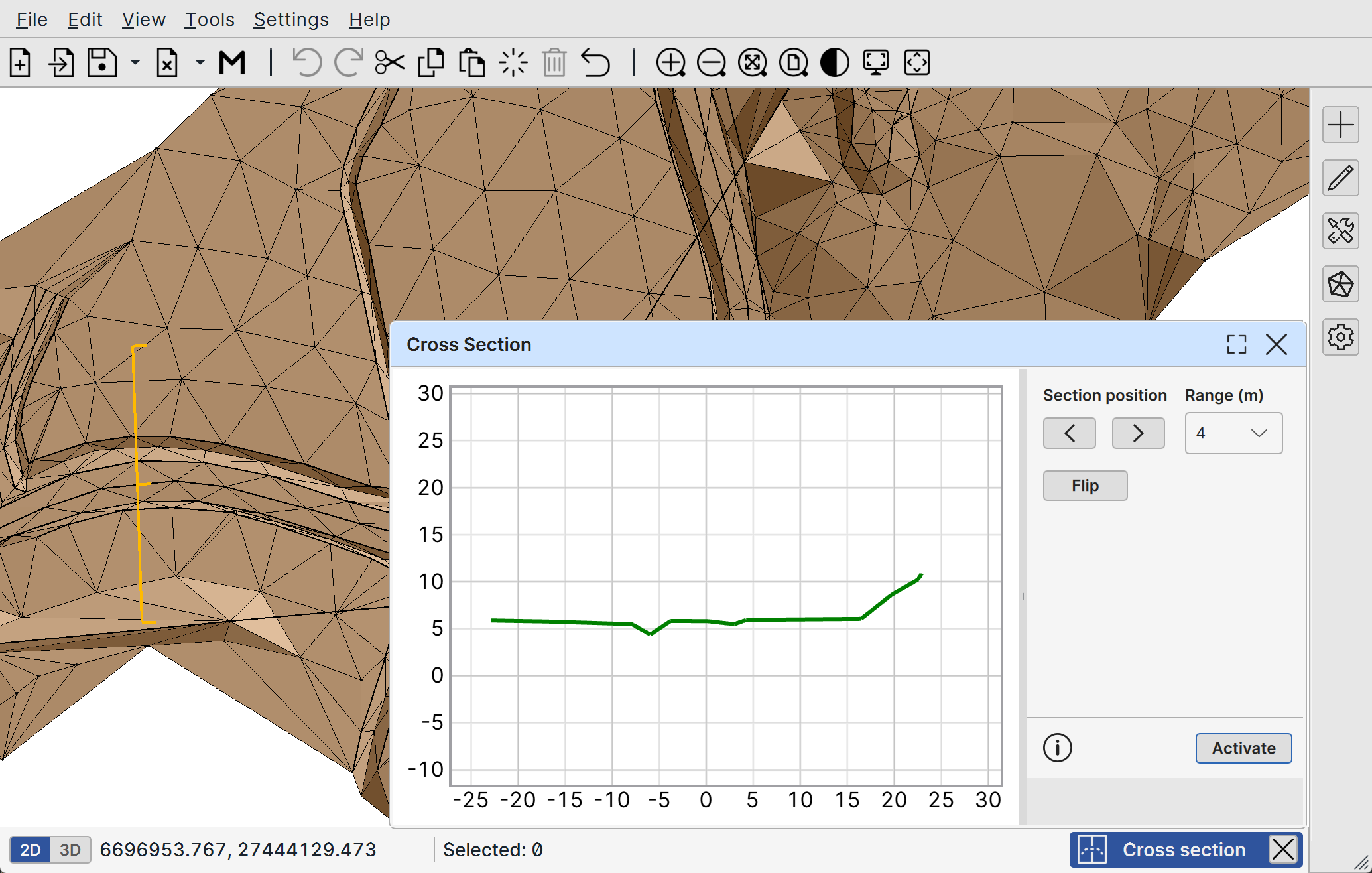
When the tool is active, the cross-section profile is displayed in a separate window that opens automatically.
Control Panel
Section position: The position of the reference line can be adjusted after creation by using the arrow buttons:
- The left arrow moves the line backward
- The right arrow moves the line forward
The cross-section profile is updated automatically when the reference line is moved.
Step (m): The movement offset amount can be adjusted here by entering the preferred step size in meters.
Flip: Flips the reference line to the opposite direction.
Activate: Activates the cross-section mode. Mode is also always automatically activated when the dialog is opened.
Shortcuts
When cross-section profile window is active:
Ctrl + R: Refresh and re-center the cross-section profile figure.
When the main window is active:
Shift + LMB: To move the cross-section reference line freely, hold shift and use left mouse button to drag and relocate the line.