 Triangulation
The terrain model is formed by triangulating either the active vector element or the marked points in the group. As a result, a new triangular mesh element is created from the element list with mm ending.
In triangulation, as a rule, the three nearest points are connected. The break line is never triangulated, but one side of the triangle is made from it. In the form of triangles, we primarily aim for equilateral triangles.
The surface ID of the point is not necessarily the same as the surface ID of the terrain model, i.e. the terrain model and the starting points in it can have different surface IDs. The file can be triangulated, even if its points are missing a surface identifier. On the other hand, points on different surfaces can be included in the same terrain model. In the future, only the surface ID of the triangle network is important. It determines the soil types in the mass calculation and the surface drawing style in the section and length section windows.
Each necessary surface must be formed with its own terrain model. One generated terrain model has only one surface. Triangulation adds a surface ID to the suffix of the file, for example mm1 or mm11.
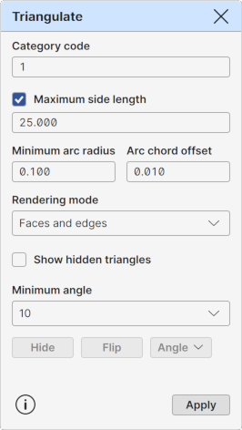
Category code
A category code for the surface. Displays the category code of the active model element and the same value is also used for new triangulated models.
Maximum side length
A maximum side length for the visible triangles. All triangles with at least one side longer that this value will be hidden. Hidden triangles are excluded from all model element operations.
The field displays the side length used for the active model element. If there are no active model elements, last used side length value is displayed.
The checkbox before the title controls the value usage. For model elements, it is unchecked by default and the value cannot be changed. For all other elements, it is checked by default and the value can be changed before creating a new model.
When applying changes to the active model element and the checkbox is unchecked, the value has no effect on the model. When checked, the side length of the active model element will be changed. Note that when applying the new side length, all manual triangle visibility changes are lost.
Minimum arc radius, Arc chord offset
Triangulated surface cannot contain arcs or circles. They must be removed before the triangulation. These two settings control how this is done.
First, all circles and arcs with radius smaller than the Minimum arc radius will be converted to points. Lone circle and arc center points will become single points. Small arcs within breaklines will become normal line points so that the original line direction before and after the removed arc will not change.
After that, all bigger arcs and circles will be converted to breaklines using the Arc chord offset setting. They are divided to small straight line segments so that the distance from the center of the line segment to the original arc is the given offset value.
Rendering mode
Triangle rendering mode.
Faces: Display only triangle faces.
Edges: Display only triangle edges.
Faces and edges: Display both triangle faces and edges.
Show hidden triangles
When turned on, hidden triangles in all model elements are also displayed.
Minimum angle
Minimum angle for keeping the triangle visible at the edge of the model. When pressing the Angle button, program checks recursively all the edge triangles of the model. If triangle has any internal corner angle smaller than the value given here, the triangle is hidden.
Hide
Starts the triangle hiding mode. Also available as a tool in the Sidebar.
Flip
Starts the triangle flipping mode. Also available as a tool in the Sidebar.
Angle
By default, performs the Minimum angle check described above.
Popup option menu has following additional operations:
Shift: Hide inner corners Hides automatically all edge triangles, who have all corner points at the same line. Requires that the network is created with breaklines embedded with it.
Apply
Creates a new model element from the active vector element. Uses automatically the Maximum side length setting for hiding too long triangles.