 Edit surface
The terrain model is formed by triangulating the active vector element. As a result, a new triangular mesh element is created in the element list.
As a main rule, the three nearest points are connected. However, if there are lines in the original vector file, triangles are created around them. This makes sure that the form of the surface stays correct.
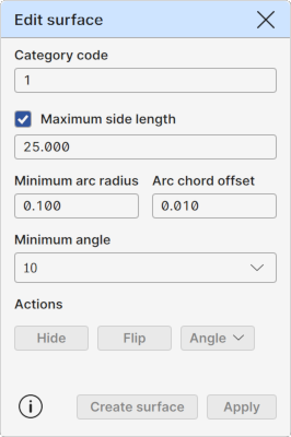
Category code
Displays the category code of the active model element. Same value is also used for new triangulated models. This ID determines the surface drawing color.
Buttons beside the fields activate code in the code list. If the code list is not currently visible, it is opened or activated automatically.
Maximum side length
A maximum side length for the visible triangles. All triangles with at least one side longer than this value will be hidden. Hidden triangles are excluded from all model element operations.
The field displays the side length used for the active surface element. If there is no active surface, last used side length value is displayed.
Note that when applying the new side length, all manual triangle visibility changes are lost.
Shorten line sections
Shortens lines found in the original vector file which exceed the Maximum side length. If the line’s length exceeds this limit, it is divided into multiple shorter lines of roughly equal length. Ensuring that all resulting lines stay within the defined size limit. This is done before the triangulation.
Surface height offset
Allows active surface height change. Positive value raises the whole surface upwards and negative value downwards.
Minimum arc radius, Arc chord offset
Triangulated surface cannot contain arcs or circles. They must be removed before the triangulation. These two settings control how this is done.
First, all circles and arcs with radius smaller than the Minimum arc radius will be converted to points. Lone circle and arc center points will become single points. Small arcs within breaklines will become normal line points so that the original line direction before and after the removed arc will not change.
After that, all bigger arcs and circles will be converted to breaklines using the Arc chord offset setting. They are divided to small straight line segments so that the distance from the center of the line segment to the original arc is the given offset value.
Minimum angle
Minimum angle for keeping the triangle visible at the edge of the model. When pressing the Angle button, the program checks recursively all the edge triangles of the model. If triangle has any internal corner angle smaller than the value given here, the triangle is hidden.
Actions
Surface edit operations.
Hide
Starts the triangle hiding mode. Also available as a tool in the Sidebar.
Shift: Hide outside of breaklines Hides all triangles outside of closed areas defined by breaklines.
Flip
Starts the triangle flipping mode. Also available as a tool in the Sidebar.
Angle
By default, performs the Minimum angle check described above.
Pop-up option menu has following additional operations:
Shift: Hide inner corners Hides automatically all edge triangles that have all corner points at the same line. Requires that the network is created with breaklines embedded with it.
Copy
Creates copy of the active surface to the element list. Suffix "copy" is appended to the name of the new surface. Otherwise it is identical to the original one.
Create surface
Creates a new model element from the active vector element. Uses automatically the Maximum side length setting for hiding too long triangles. Checks if the Trim line sections is selected and performs line trimming before triangulation.
Apply
Applies changes to the active model element.